A current sensor should not be qualified only from its datasheet.
It must be qualified according to the customer application, especially in harsh environments.
1. Why the Datasheet Is Not Enough ?
A datasheet is always the starting point. It gives the engineer the first level of confidence: accuracy, bandwidth, offset, isolation, operating temperature, supply voltage, mechanical dimensions. It tells us what the current sensor is designed to do under defined and controlled conditions.
But in a real application, the sensor is not working inside a datasheet.
It is mounted on a PCB, It is close to a power stage, It sees real current profiles and It is exposed to heat, switching noise, magnetic fields, mechanical constraints, and sometimes limited cooling.
This is where the difference appears between product specification and application performance. On paper, two sensors can look similar. In the final system, they may behave very differently.
A current sensor can meet its datasheet values during standard tests, but once integrated into the customer application, its performance can be influenced by the environment around it. A nearby MOSFET bridge can increase local temperature. A busbar geometry can modify magnetic coupling. A noisy gate driver area can affect the signal. A compact enclosure can reduce thermal dissipation.
The sensor has not changed.
The conditions around it have.
That is why the datasheet alone is not enough for harsh applications. The real question is not only : Does the sensor meet its datasheet ?
The real question is : Does the sensor keep the required accuracy, stability, and reliability inside the customer system ?
This is the purpose of application-based qualification. It does not replace the datasheet. It completes it. The datasheet defines the expected performance of the product. The application qualification verifies that this performance remains valid under real operating constraints.
In demanding environments, this difference is critical. Because a current sensor is often part of the control loop, the protection system, or the safety chain. If the measurement drifts, becomes noisy, or reacts differently under thermal stress, the impact is no longer only a sensor issue. It becomes a system-level risk.
2. Start from the Customer Use Case
Before qualifying a current sensor, the first step is not to look for the best number in the datasheet. The first step is to understand where the sensor will be used, how it will be integrated, and what the customer expects from the measurement.
A current sensor does not measure a theoretical current. It measures a real current inside a real system. This current may be continuous, pulsed, transient, repetitive, or linked to a fault condition. The same current value can represent very different constraints depending on the application. For example, 500 A RMS during ten minutes is not the same stress as 500 A peak during a few milliseconds. The impact on temperature, accuracy, response time, and long-term reliability will be completely different.
This is why the customer use case must drive the qualification process. The mission profile defines the real conditions: current level, waveform, duration, ambient temperature, cooling conditions, mechanical position, nearby power components, EMI environment, and required accuracy. Without this information, the qualification remains too generic.
In a demanding application, the question is not simply whether the sensor is accurate. The question is whether it remains accurate under the customer’s real operating conditions. A sensor may perform very well in standard laboratory conditions, but its behavior can change when it is placed close to a hot power stage, exposed to switching noise, mounted around a specific busbar geometry, or installed inside a compact enclosure with limited airflow.
Starting from the customer use case makes the qualification more realistic. It allows the test conditions to represent the actual constraints of the final system, not only ideal conditions. It also helps define the right acceptance criteria: acceptable error, offset drift, thermal rise, noise level, bandwidth, insulation requirement, and safety margin.
This approach changes the way we qualify the product. We do not only ask, What is the sensor specification? We ask, What does the customer system really need from this measurement?
3. Harsh Environments Change the Qualification Criteria
In a standard qualification, the current sensor is often checked against defined electrical conditions: nominal current, accuracy, offset, bandwidth, insulation, and temperature range. This is necessary, but in harsh environments it is not sufficient.
A harsh environment adds stress around the measurement. The sensor is no longer evaluated only as an electronic component. It becomes part of a system exposed to heat, high current, switching noise, mechanical constraints, vibration, humidity, and sometimes strong electromagnetic disturbances.
In this context, the qualification criteria must change. It is not enough to verify that the sensor works at room temperature or under a clean current waveform. The real question is whether the sensor can maintain its performance when the system is under stress.
For example, in a power electronics application, the sensor may operate close to MOSFETs, IGBTs, gate drivers, busbars, or magnetic components. These elements can create thermal gradients, electrical noise, and magnetic coupling. The sensor may still function, but its measurement can be affected by offset drift, gain variation, noise on the output signal, or reduced repeatability.
This is why harsh-domain qualification must include more than basic electrical validation. It must evaluate the sensor under realistic stress conditions: high RMS current, peak current, thermal rise, transient events, EMI exposure, mechanical integration, and long-duration operation.
The objective is not only to confirm that the product survives. The objective is to confirm that it continues to measure correctly.
In demanding applications, a current sensor is often connected to protection, control, or monitoring functions. If the measurement becomes unstable, the risk is not limited to the sensor itself. It can affect the full system behavior.
4. Thermal Qualification Under Real Load
Thermal qualification is a critical step when a current sensor is used in a demanding application. The goal is not only to check if the sensor can survive the temperature. The goal is to verify if the sensor can keep a stable and accurate measurement while the system is operating under real load.
In a datasheet, the temperature range gives an important limit. But in the customer application, the sensor is exposed to a specific thermal environment. The heat does not come only from the sensor itself. It can come from the busbar, the PCB, the MOSFETs, the IGBTs, the gate drivers, the connectors, or the enclosure. This means that the local temperature around the sensor can be very different from the ambient temperature.
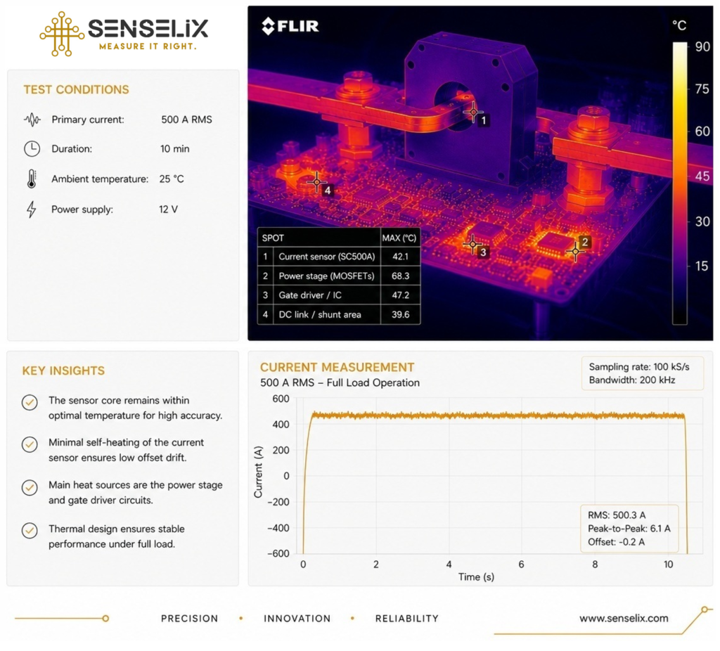
This is why the sensor must be tested under representative load conditions. For example, applying 500 A RMS during 10 minutes at 25 °C ambient temperature gives a much clearer view of the real behavior than a simple static check at room temperature. During this test, we can observe the temperature rise, identify the hot spots, and verify whether the sensor output remains stable during the full-load condition.
The thermal image is useful because it shows the complete environment around the sensor. Sometimes the sensor is not the main heat source. The highest temperature may come from the power stage or from nearby components. But even in that case, the sensor is still affected by this environment. Heat can influence offset, gain, signal stability, and long-term reliability.
A good thermal qualification must therefore combine two measurements: the temperature behavior and the electrical measurement behavior. It is not enough to say that the sensor remains within its temperature limit. We also need to confirm that the current measurement remains accurate and repeatable while the temperature is rising.
This is the real value of testing under load. It shows whether the sensor can perform inside the customer system, not only under ideal laboratory conditions.
5. System-Level Measurement Validation
After checking the thermal behavior under real load, the next step is to validate the measurement at system level. At this stage, the question is no longer only whether the sensor works. The question is whether the measurement remains usable, stable, and reliable when the complete system is operating.
A current sensor is often connected to important system functions: control loop, power regulation, protection, monitoring, or fault detection. This means that the output signal must stay clean and consistent, not only in ideal conditions, but also when the application is stressed.
During system-level validation, the sensor output should be observed while the real current profile is applied. The objective is to check if the measured current follows the expected behavior without excessive noise, drift, delay, or instability. A correct RMS value is important, but it is not the only criterion. The signal quality also matters.
Several parameters should be verified: offset stability, gain accuracy, noise level, peak-to-peak ripple, response time, bandwidth behavior, repeatability, and behavior during transients. These elements define whether the measurement can really be trusted by the system.
For example, a sensor may give the correct value at steady state, but show too much noise during switching events. Another sensor may be accurate at room temperature, but drift after several minutes at full load. In both cases, the datasheet may still look acceptable, but the application performance is not fully validated.
System-level validation allows us to see these effects before the product is deployed. It connects the electrical measurement to the real environment: current waveform, power stage activity, temperature rise, EMI, mechanical integration, and operating duration.
The goal is not only to obtain a number. The goal is to confirm that the sensor output remains stable enough for the customer’s control, protection, and monitoring needs.
6. Integration Matters
A current sensor is never qualified only by its internal design. Its final performance also depends on how it is integrated into the customer system.
The same sensor can give different results in two different applications. Not because the sensor itself has changed, but because the environment around it is different. The conductor position, the busbar geometry, the PCB layout, the distance from power components, the cooling path, and the signal routing can all influence the measurement.
In high-current applications, integration becomes even more critical. A busbar placed too close to another current path can create magnetic coupling. A sensor installed near MOSFETs, IGBTs, transformers, or inductors can be exposed to additional electromagnetic disturbances. Poor signal routing can add noise. Limited airflow can increase local temperature and affect measurement stability.
Mechanical integration also matters. The position of the conductor inside or around the sensing area must be controlled. Small misalignments can affect accuracy or repeatability, especially when the system is exposed to vibration, thermal cycling, or mechanical stress.
This is why sensor qualification must include the real integration conditions, or at least a representative setup. It is not enough to test the sensor alone on a clean bench if the final product will operate inside a compact, noisy, and thermally constrained power system.
A good sensor can lose performance if it is poorly integrated. In the same way, a well-designed integration can help the sensor deliver stable and accurate measurements even in a harsh environment.
Application qualification must therefore look at the complete measurement chain: the sensor, the conductor, the mechanical position, the thermal environment, the electrical noise, the signal path, and the system constraints.
7. From Product Qualification to Application Qualification
Traditional product qualification answers one main question: does the sensor meet its datasheet specification? This is an important step. It confirms that the product is compliant with its defined electrical, thermal, mechanical, and insulation limits.
But for a demanding customer application, this is only part of the validation.
Application qualification goes further. It asks whether the sensor can meet the customer requirements inside the real operating environment. The current level, waveform, duration, temperature, EMI, mechanical position, cooling conditions, and safety constraints are all considered part of the qualification.
This changes the qualification logic. The objective is no longer only to validate a standard product. The objective is to validate a measurement solution for a specific mission profile.
For example, a sensor may be qualified in production according to its datasheet limits. But if the customer application exposes it to high RMS current, nearby switching devices, compact mechanical integration, and limited airflow, additional validation is needed. The sensor must prove that it can keep the required accuracy and stability in that specific environment.
This is where the difference between product compliance and application confidence becomes clear.
Product qualification confirms that the sensor is correctly designed and manufactured. Application qualification confirms that the sensor is correctly selected, integrated, and used for the customer system.
Both are necessary, but they do not answer the same question.
In harsh domains, the customer does not only need a sensor that passes standard tests. The customer needs a measurement that remains reliable when the system is exposed to real stress.
8. Conclusion
In demanding applications, selecting a current sensor cannot be reduced to reading a datasheet. The datasheet remains essential, but it gives only the first level of information. It defines what the product can achieve under controlled conditions.
The real validation starts when the sensor is tested against the customer application.
This means understanding the mission profile, the current waveform, the thermal environment, the mechanical integration, the EMI constraints, and the accuracy expected by the system. Only then can the sensor be qualified in a way that reflects its real operating conditions.
For harsh environments, this approach is critical. The sensor may be used for control, protection, monitoring, or safety-related functions. Its measurement must remain stable when the system is under stress: high current, temperature rise, switching noise, vibration, or limited cooling.
A good qualification process does not only prove that the sensor works. It proves that the measurement can be trusted inside the final application.